86 Results
View results:
Sort by:

The data exchange between RFEM 6 and Allplan can be done using various file formats. This article describes the data exchange of a determined surface reinforcement using the ASF interface. This allows you to display the RFEM reinforcement values as level curves or colored reinforcement images in Allplan.

Moment frame design according to AISC 341-16 is now possible in the Steel Design add-on of RFEM 6. The seismic design result is categorized into two sections: member requirements and connection requirements. This article covers the required strength of the connection. An example comparison of the results between RFEM and the AISC Seismic Design Manual [2] is presented.

Creating a validation example for Computational Fluid Dynamics (CFD) is a critical step in ensuring the accuracy and reliability of simulation results. This process involves comparing the outcomes of CFD simulations with experimental or analytical data from real-world scenarios. The objective is to establish that the CFD model can faithfully replicate the physical phenomena it is intended to simulate. This guide outlines the essential steps in developing a validation example for CFD simulation, from selecting a suitable physical scenario to analyzing and comparing the results. By meticulously following these steps, engineers and researchers can enhance the credibility of their CFD models, paving the way for their effective application in diverse fields such as aerodynamics, aerospace, and environmental studies.

Everything is online. The same is true for the Dlubal licenses for RFEM 6, RSTAB 9, and RSECTION. This article contains information about using and managing online licenses, reserving licenses, checking the license validity, and moving authorizations between the licenses.

The events of recent years remind us of the importance of earthquake engineering in seismic regions. For you as an engineer, the design of structures in earthquake-prone areas is a constant trade-off between economic efficiency – the financial possibilities – and structural safety. If a collapse is inevitable, engineers must estimate how it will affect the structure. This article aims to provide you with an option on how to perform this estimation.

When a concrete slab is set upon the top flange, its effect is like a lateral support (composite construction), preventing problems of torsional buckling stability. If there is a negative distribution of the bending moment, the bottom flange is subjected to compression and the top flange is under tension. If the lateral support given by the stiffness of the web is insufficient, the angle between the bottom flange and the web intersection line is variable in this case so that there is a possibility of distortional buckling for the bottom flange.

A new capability within RFEM 6 when designing concrete columns is being able to generate the moment interaction diagram according to the ACI 318-19 [1]. When designing reinforced concrete members, the moment interaction diagram is an essential tool. The moment interaction diagram represents the relationship between the bending moment and axial force at any given point along a reinforced member. Valuable information is shown visually like strength and how the concrete behaves under different loading conditions.

The properties of the connection between a reinforced concrete slab and a masonry wall can be correctly considered in the modeling using a special line hinge that is available in RFEM 6. This article will show you how to define this type of hinge using a practical example.

This article shows you how to create contacts between two or more parallel surfaces by controlling the transfer of forces between them.

This article will show you how to properly consider the connection between surfaces that touch each other on one line with the help of line hinges in RFEM 6.
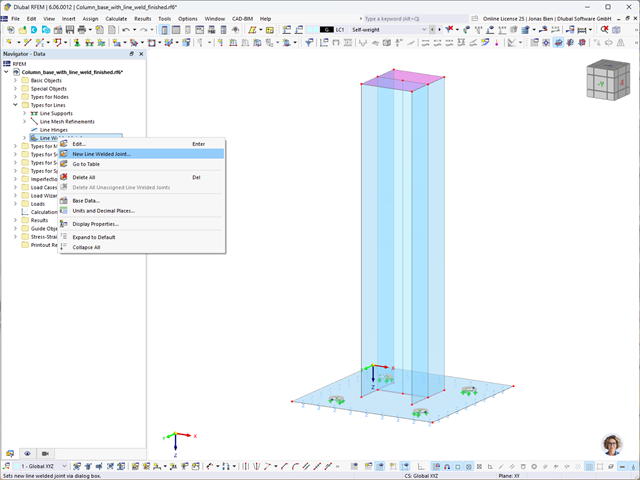
In RFEM 6, it is possible to define line welds between surfaces and calculate the weld stresses using the Stress-Strain Analysis add-on. This article will show you how to do it.
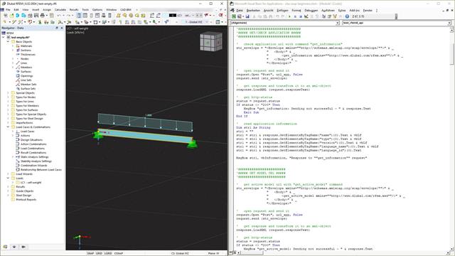
Webservice is a communication between machines and programs. This communication is provided via the network and can, therefore, be used by any program that can send and receive strings via the HTTP protocol. RFEM 6 and RSTAB 9 provide an interface based on these cross-platform webservices. This tutorial shows the basics using the VBA programming language.

According to EN 1992-1-1 [1], a beam is a member of which the span is no less than 3 times the overall section depth. Otherwise, the structural element should be considered as a deep beam. The behavior of deep beams (that is, beams with a span less than 3 times the section depth) is different from the behavior of normal beams (that is, beams with a span that is 3 times greater than the section depth).
However, designing deep beams is often necessary when analyzing the structural components of reinforced concrete structures, since they are used for window and door lintels, upstand and downstand beams, the connection between split-level slabs, and frame systems.

The new generation of RFEM software is an intuitive, powerful, and easy-to-handle 3D FEA program that meets all the latest demands in modeling, calculation, and structural design. The modern design concept, as well as the introduction of new features, make the program even more innovative and user-friendly. The main differences between RFEM 6 and its previous version, RFEM 5, are discussed in the following text.

When modeling and designing glass panes in RF-GLASS, you have two different options for the FE mesh settings.
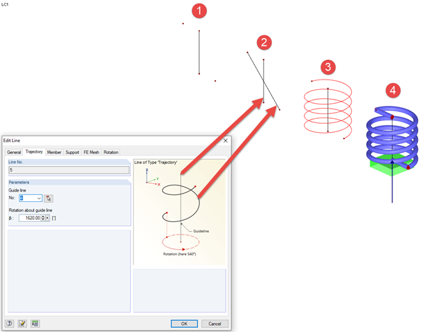
In RFEM, you can create screw lines using the "Trajectory" type line. To do this, you need a center line/guide line around which the line can be modeled, as well as a start and end point. Then, you can create a "Trajectory" type line between the start and end points; this initially appears as a straight line.

If members aligned in space meet in a node, the local x- or y-axes of the members do not lie in one plane, since the local z-axes are aligned in the plane of gravity.

When modeling structural bearing systems, especially hall structures, some substructures of a foundation with no influence on the rising structure are not modeled in RFEM/RSTAB. In the case of hall structures, these are, for example, reinforced concrete floor slabs, strip foundations, and the ties between column foundations.
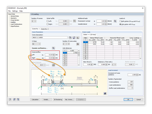
In the event of converting or extending a hall, the building owner may want to add a second or third crane to an existing crane runway. Since the original design usually does not consider other cranes, a common solution is to design a minimum distance between the cranes. This is done via the crane technology settings.

In RFEM, you can display the contact properties between two surfaces by means of contact solids. Among other things, you should ensure that both contact surfaces of a contact solid have the same integrated objects. Therefore, when modeling the contact surfaces, we recommend using the copy function in order to create the second contact surface.

In RFEM, you can display the contact properties between two surfaces by means of contact solids.
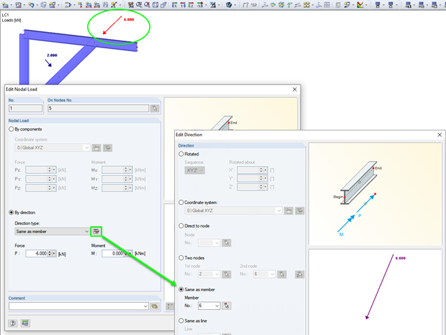
RFEM and RSTAB provide various options for entering nodal loads. These implemented features allow the user to define the nodal loads in relation to different components in space.
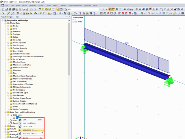
It often happens that loads should be copied as a template into another load case, for example. This article describes two ways to copy loads between load cases.

In the age of BIM, data exchange between the various disciplines of structural engineering is becoming increasingly important. Since each software has its own specifications with regard to the description of cross-sections and materials, RFEM and RSTAB offer a conversion table (mapping file).

General thin-walled cross-sections often have asymmetrical geometries. The principal axes of such sections are then not parallel to the horizontally and vertically aligned axes Y and Z. When determining the cross-section properties, the angle α between the center-of-gravity axis y and the principal axis u is determined in addition to the principal axis-related moments of inertia.

Once you have determined the final tendon geometry in RF‑TENDON, exporting the model to a CAD program can be useful. For this purpose, the module includes the option to export the file in the .dxf file format. You can select the export function by right-clicking the workspace. After selecting the DXF format and the storage location, additional settings can be made.

To simulate a support clearance in a connection between members, you can use the "Diagram" function for member hinges. To use this function, first define the relevant degree of freedom as release. Then, you can select the "Diagram" function from the drop‑down list.

For designing glass in the RF‑GLASS add‑on module, you can use one of two calculation methods: a 2D or a 3D calculation. The main difference between these design options is the automatic modeling of the layers in a temporary model. In a 2D calculation, each layer is generated as a surface element (plate theory); in a 3D calculation, it is generated as a solid. Depending on the selected layer composition, you can either select an option or find it preselected by the program.

For solids, there is another option for the FE mesh setting. You can arrange a layered FE mesh in addition to a holistic FE mesh refinement. For this option, you can perform a defined division of the solid with finite elements between two parallel surfaces. This option is particularly suitable for very large solid geometries with a low height.

With the RF-/TIMBER Pro add-on module, you can perform the vibration design known from DIN 1052 for the design according to EN 1995-1-1. In this design, the deflection under permanent and quasi-permanent action at the ideal one‑span beam may not exceed the limit value (6 mm according to DIN 1052). If you consider the relation between the natural frequency and the deflection for a hinged single-span beam subjected to a constant distributed load, the 6 mm limit value results in a minimum natural frequency of about 7.2 Hz.